Lesson 1.1 – Spur Gears
Learn how spur gears change speed and torque in robots. Build and code simple, idler, and compound gear trains using VEX V5 to see how gear ratios affect motion.
← Back to Robotics HomeLesson Overview
What you will learn and build in this lesson.
In this lesson you will explore spur gears, the most common type of gear in VEX robotics. You will learn how spur gears transmit motion, how to identify driver, driven, and idler gears, and how to calculate gear ratios. You will build and code three different gear trains: (1) a simple 2-gear train, (2) a 3-gear idler train that keeps the same direction as the driver, and (3) a compound gear train that creates very high torque to lift a heavy weight.
- Describe what a spur gear is and how it works.
- Label driver, driven, idler, and compound gears in a gear train.
- Calculate gear ratios using gear tooth counts.
- Explain how changing gear ratios affects speed and torque.
- Build and code simple, idler, and compound gear trains with VEX V5.
- Choose a gear setup that fits a goal (speed, power, or direction).
- Part A: Concepts and vocabulary for spur gears.
- Part B: Visual models and real-life analogies.
- Part C: Three build-and-code activities:
- Activity 1: Simple (2) Gear Train (Power vs Speed)
- Activity 2: (3) Gear Idler Train (Keep the Direction)
- Activity 3 – Compound train (heavy-weight lift)
- Part D: “Check Your Understanding” questions.
Gear Ratios in Action
Concepts & Vocabulary
Key ideas you need before building.
1. What Is a Spur Gear?
A spur gear is a round wheel with straight teeth around the edge. The teeth are parallel to the shaft and they mesh with other spur gears on parallel shafts. When one spur gear turns, its teeth push the teeth of the next gear, causing it to turn.
- Spur Gear: Gear with straight teeth on parallel shafts.
- Gear Train: Two or more gears working together.
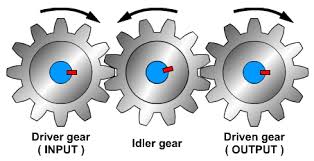
- Driver Gear: The gear connected to the motor (input).
- Driven Gear: The gear that is turned by the driver (output).
- Idler Gear: A middle gear that changes direction but not the ratio.
- Compound Gear: Two gears on the same shaft that spin together.
- Gear Ratio: Driven gear teeth ÷ driver gear teeth.
- Speed: How fast something spins (e.g., rotations per minute).
- Torque: The twisting force that can move or lift things.
Formula:
Gear Ratio = Driven Gear Teeth ÷ Driver Gear Teeth
- Gear Ratio > 1 → more torque, less speed (“gearing down”).
- Gear Ratio < 1 → more speed, less torque (“gearing up”).
- Idler gears flip direction but keep the same overall ratio.
- Compound gear trains multiply stages for very high torque.
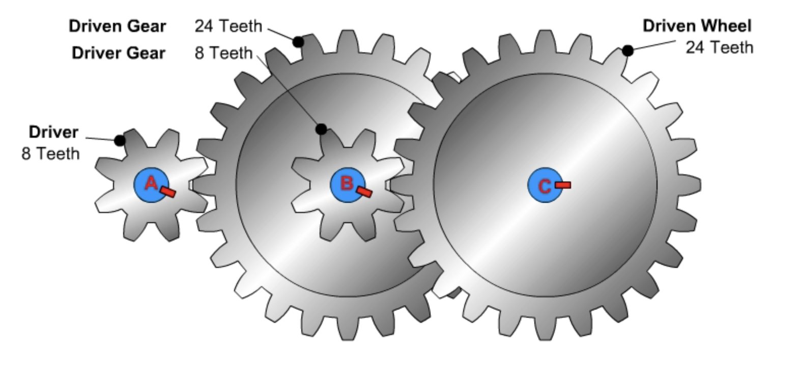
2. Example Gear Ratios with VEX Gears
Common spur gears in VEX V5: 12T, 36T, 60T, 84T. “T” means number of teeth.
| Gear Train | Driver Teeth | Driven Teeth | Gear Ratio (Driven ÷ Driver) | What It Does |
|---|---|---|---|---|
| Simple Power Train | 12T | 36T | 36 ÷ 12 = 3:1 | Strong torque, slow speed |
| Simple Speed Train | 36T | 12T | 12 ÷ 36 = 1:3 | Fast speed, low torque |
| Idler Train | 12T → 36T → 12T | Overall | 12 ÷ 12 = 1:1 | Same speed & torque, different direction & spacing |
| Compound High-Torque | 12T → 36T, 12T → 60T | Overall | 3 × 5 = 15:1 | Very strong torque, very slow |
Gear Ratios Calculator
Build your own gear trains on paper first, then use this calculator to check the math. Enter as many gear pairs as you need for both simple (linear) trains and compound trains.
Simple / Linear Gear Trains
Use this when your driver turns the final driven gear through up to three idlers. Enter between 2–5 gears to include the driver, optional idlers, and the final driven gear.
Compound Gear Trains
Use this when two gears share the same shaft. Each new shaft adds a driven gear and a driver gear together. Start with the motor shaft, then add up to three compound shafts before the final driven shaft (maximum 5 shafts total).
Visual Models
Ways to picture what the gears are doing.
Imagine shifting gears on a bicycle:
- Low gear: Easy to pedal, good for hills, but slow.
- High gear: Hard to start, but very fast on flat ground.
This is like gearing down and gearing up in your robot. You choose a gear train based on whether you care more about power or speed.
As you build, compare your real robot to these diagrams. Make sure you can point to each gear and say what its job is.
Build & Code Activities
Follow these steps in order during class.
Shared Coding Setup
You will use the same basic program for all three builds so you can compare them fairly.
- Open VEXcode V5 and start a new Blocks project.
- Click Devices → Add a Device → Motor and pick the port of your motor.
- Name the motor
GearMotor.
Standard Test Program (use this for every build):
- When started → set
GearMotorvelocity to 50%. - Spin
GearMotorforward. - Wait 5 seconds.
- Stop
GearMotor.
You will run this same program on your simple gear train, your idler train, and your compound train to see how each design behaves.
Activity 1: Simple (2) Gear Train (Power vs Speed)
In this activity you build two versions of a 2-gear train: one that is strong but slow, and one that is fast but weak.
What You Need
- VEX V5 Brain, Smart Motor, battery, cables
- At least 2 shafts, bearings, shaft collars, spacers
- Spur gears: 12T and 36T (or similar)
- Structural pieces
- A wheel or small drum as the output
A. Power Setup (12T → 36T)
- Mount the motor to a piece of structure.
- Place a shaft in the motor and add a 12T gear (driver). Lock it with collars.
- Mount a second shaft with a 36T gear (driven) so the teeth mesh with the 12T.
- Attach a wheel or drum to the driven shaft.
- Spin the gears by hand. They should move smoothly without rubbing metal.
B. Speed Setup (36T → 12T)
- Now make a new setup where the 36T gear is on the motor (driver).
- Put the 12T gear on the output shaft (driven) with a wheel.
- Check that the gears mesh and spin freely.
Coding & Observations
- Download and run the Standard Test Program on the power setup.
- Watch how quickly the output turns and how “strong” it feels.
- Repeat with the speed setup using the exact same program.
- Record in your notes:
- Power ratio: 36 ÷ 12 = 3:1 → strong, slow output.
- Speed ratio: 12 ÷ 36 = 1:3 → fast, weak output.
Activity 2: (3) Gear Idler Train (Keep the Direction)
In this activity you add an idler gear so the final gear spins in the same direction as the driver, while keeping the gear ratio the same.
What You Need
- Same parts as Activity 1
- One extra gear for the idler (for example, another 36T gear)
Steps
- Start with a 2-gear 1:1 setup (for example, 12T driver and 12T driven).
- Run the Standard Test Program and notice: the driver and driven gears spin in opposite directions.
- Add a third gear between them on its own shaft. This is your idler gear.
- Make sure all three gears mesh correctly.
- Run the same program again and watch the final driven gear.
What to Record
- Draw your 3-gear train and label driver, idler, and driven gears.
- Write down the tooth counts on the first and last gears.
- Calculate the overall gear ratio (it should still be 1:1).
- Explain in one or two sentences how the idler gear changed the direction.
Activity 3 – Compound Winch & Pull Test
Build a compound gear train winch that pulls a load with string on a pulley. You will compare three builds that start with 12T drivers and progressively larger compound driven gears (36T → 60T → 84T) while the final winch drum remains a 36T driven gear. The goal is to see how the ratio on the input side controls torque, speed, and how much work the robot can do.
What You Need
- VEX V5 Brain, Smart Motor, battery, and cables (start with the 18:1 cartridge, but keep 36:1 or 6:1 handy)
- Programming device running VEXcode V5 to spin the motor (winch) for a timed test
- Gears: lots of 12T drivers plus 36T, 60T, and 84T driven gears
- Three shafts (A, B, C), bearings, collars, spacers, and structural rail or plates
- Drum/winch or pulley on the final shaft, strong string, hanging weights, and a ruler or tape measure
Build Steps
- Build A – Three 12T → 36T stages (baseline 27:1):
- Shaft 1 (motor): 12T driver → meshes with 36T on Shaft 2.
- Shaft 2: 36T driven shares a shaft with another 12T driver → meshes with 36T on Shaft 3.
- Shaft 3: Repeat one more 36T driven with a final 12T that drives a 36T on Shaft 4. Attach the winch drum to Shaft 4.
- Build B – Swap the middle compound driven gear to 60T (higher torque 45:1):
- Keep the first stage (12T → 36T) the same as Build A.
- Replace the second stage driven gear (on the compound shaft before the drum) with 60T while keeping the final 36T drum gear.
- Build C – Swap the compound driven gear to 84T (maximum torque 63:1):
- First stage stays 12T → 36T.
- Use an 84T driven gear on the compound shaft (still paired with a 12T driver going into the final 36T drum).
- Secure the string on the drum, guide it over a pulley anchored to the table, and attach a weight hook.
- Program the VEX V5 Brain to spin the motor forward for 5 seconds at 50% power so every pull test is fair.
Gear Ratio Math
| Build | Stage Breakdown | Overall Ratio | What to Expect |
|---|---|---|---|
| Build A (36T stack) | (36 ÷ 12) × (36 ÷ 12) × (36 ÷ 12) | 27:1 | Good torque, still reasonable speed |
| Build B (60T compound) | (36 ÷ 12) × (60 ÷ 12) × (36 ÷ 12) | 45:1 | Stronger torque, noticeably slower drum |
| Build C (84T compound) | (36 ÷ 12) × (84 ÷ 12) × (36 ÷ 12) | 63:1 | Maximum torque, slowest drum speed |
Pull Test Data
Run the same winch program for every build. Use a spring scale or spend weights to determine how much mass each gear ratio can lift. Record how high the load travels in 5 seconds and note any slipping or stalling.
| Build | Max Load Pulled (g) | Height Raised in 5 s (cm) | Torque vs Speed Notes |
|---|---|---|---|
| Build A – 36T stack | |||
| Build B – 60T compound | |||
| Build C – 84T compound |
Engineering Notebook Reminder: Copy both the Gear Ratio Math table and this Pull Test Data table into your notebook, then fill in every column with your measured data and observations.
- 36:1 cartridge (~100 RPM): Highest base torque. Output torque ≈ motor torque × gear ratio.
- 18:1 cartridge (~200 RPM, standard): Balanced torque/speed. Great for comparing classroom data.
- 6:1 cartridge (~600 RPM): High speed but low torque. Needs very small loads or low ratios.
Example: If the 18:1 motor produces 0.25 N·m at the shaft, Build B (45:1) delivers about 11.25 N·m before friction losses. Swap in the 36:1 cartridge to double the motor torque, then multiply by the gear ratio to predict how much additional load your winch can lift.
Check Your Understanding
Exit Ticket: answer each prompt, then download, print, and put into your engineering notebook (or copy the questions and answers in your notebook).